After building my first semi-portable solar power station and then DIY powerwall, I decided it was time to take my battery building to the next level. I had access to good lithium-ion cells from cancelled ebike projects, but what to make?
Design Choices
A more compact 12V system would be a natural choice, but standard nickel manganese cobalt (NMC) lithium-ion cells are not a great choice due to their voltage range (see note below). A 7S system (seven cell strings in series) works really well with 24V inverters and standard low-cost solar equipment (including charge controllers and automotive-style fuses). 7S it is!
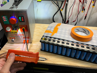 |
| Battery build in process, showing the spot welder |
I could also have made a 48V portable system to match the powerwall, but I figured it would be less compact and less appropriate to directly power portable equipment. Also it would need more/larger solar panels to reach a supply voltage higher than the battery (to use standard charge controllers).
Note on nomenclature: lithium iron phosphate (LFP, LiFePO4) cells are also technically a type of lithium ion, but when people say “lithium ion” they generally mean NMC. LFP cells have the advantage of less volatility, but lower density (volumetric and gravimetric).
Note on lithium ion usage for 12V systems: since the typical cell operating range is 3-4.2V, a 3S system would give 9-12.6V and 4S gives 12-16.8V. This might be fine for some specific 12V loads, but inverters generally have an input range no wider than 10-15V (unless you splurge on a Victron). So no matter which you choose, there is 20-40% capacity loss by not being able to take full advantage of the high or low end of the voltage range.
Components
My available cells were Samsung INR21700-50E. Each one with a capacity of 5Ah (18Wh) and max continuous discharge rating of 10A. To fit perfectly in the toolbox I was planning to dedicate to this project, I chose a grid of 7S18P. With 18 cells in parallel, that’s a total of 126 cells, 2268Wh. That’s bigger than all but the most expensive portable power stations!
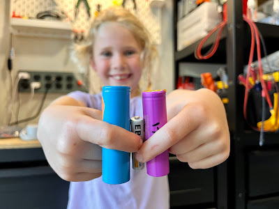 |
| Comparison of cell sizes: from left to right, 21700 (21mm dia x 70mm long), AAA (10.5mm x 44.5mm long), and 18650 (18mm dia x 65mm long) |
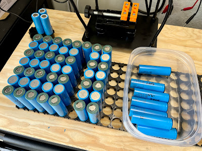 |
| I need cells... lots of cells. |
Key components to build a battery (this is what I actually used), in addition to the cells, of course:
- Cell holders
- Nickel strip, 0.15mm ladder-style
- Insulating rings (bonus safety insurance)
- Daly 7S 60A BMS with Bluetooth and display
- 8AWG wire (this is a good brand; unfortunately not what I used)
- 10AWG butt connectors (my 8AWG wire fit in these but maybe because my wire wasn't as thick as claimed. Same brand also makes an 8AWG version.)
- XT90 connectors (female on battery side)
- Kapton tape
- Big pack heat shrink
- Spot welder
For spot welding, I inherited a Sunkko 709A. It works well enough for 0.15mm nickel with the settings maxed-out. If I was buying one fresh for light-duty use, I like the ones based on super-capacitors rather than LiPo pouches (which seem to wear out quickly), though I haven’t tried one yet. The DIY community seems to swear by the kWeld for more serious usage.
And make sure that the nickel strip and the cell holders chosen have the exact same spacing. Mine were slightly off, but I was just able to make it work across 18 cells.
Let’s build it!
 |
| Left to right is 18 cells in parallel, top to bottom is 7 cells in series: 7S18P |
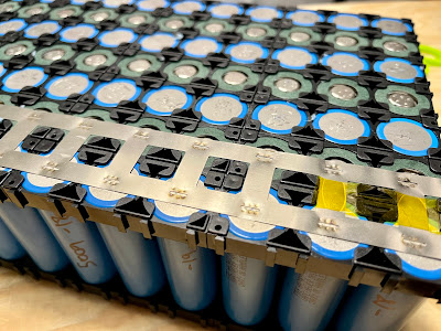 |
| First ever spot welds. I'm sure they can be improved but they will work! |
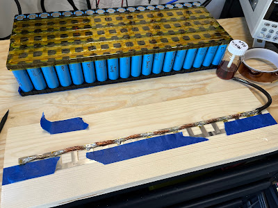 |
| Soldering the main positive and negative connections before spot welding |
For the main positive and negative connections, the easy way is just to solder a wire on the corner; many commercial packs even do that. But for way better current-carrying capacity, I can solder the wire all long one side of the nickel strip ladder BEFORE spot welding it to the battery. This avoids excess heat into the cells. Then fold it over to be compact. 8AWG wire plus effectively two layers of nickel the whole length of the battery makes for lots of ampacity.
 |
| BMS monitoring/balance leads along the side |
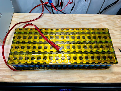 |
| Completed battery assembly with layers of Kapton tape to avoid shorts |
 |
| BMS attached and measuring the total capacity with an electronic DC load. |
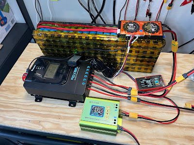 |
| Working solar power system! Renogy Rover solar charge controller (black box on left) and MPT-7210A boost charger (green box on bottom) for charging other batteries/bikes. |
I kept the solar power system running with the battery on my bench top for 6months until I finally sealed it up and finished the power station. I thought maybe I would need to tweak something but no! Ultimately the construction is straightforward.
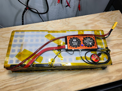 |
| Prepping the pack to be wrapped |
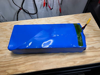 |
| All wrapped up! |
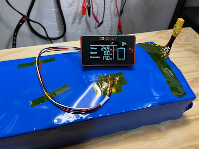 |
| Live pack, ready to go. I made a slit in the heat shrink where the display wires connect to the BMS, then connected the display. |
More about the full portable system in the next post.
How would you improve this battery?
Cheers,
Mike

No comments :
Post a Comment
If you're having trouble commenting with your google account, try enabling 3rd party cookies. In Safari, that means un-checking "prevent cross-site tracking" under privacy settings. Super annoying I know!